|
|
Phy.203 Links:
» Syllabus
» 203§2 web page
- - - Unit 1 - - -
» topic 1 (ch.20)
» topic 2 (21+23)
» topic 3 (22+23)
. . . here! ⇒
- - - Unit 2 - - -
» topic 4 (24)
» topic 5 (½25+26)
- - - Unit 3 - - -
» topic 6 (25+½18)
» topic 7 (18+19)
» topic 8 (17)
- - - Unit 4 - - -
» topic 9 (29+28)
» topic10 (30)
- - MU Physics 2 - -
» MU-online
(BlackBoard site)
» 204 §2 web page
» 204 §2 syllabus
- - Off-Campus - -
» PhysicsForums
(human hw help)
» hyperphysics
(detailed e-book)
» Knight 4th ed.
(pdf download)
|
|
|
|
College Physics 2 (203) - Topic Three Assignments & notes
Science 159 (below 3rd Ave ramp) foltzc@marshall.edu don't phone - stop in!
Topic 3 (Electric Current, Power, & Resistance)
Readings for Topic 3 (Knight,Jones,Field 4th): Ch.22 + Ch.23
|  |
Plan for Unit 1 Exam on thR.Feb.08
Plan for Topic 3 Quiz on Tue.Feb.06 - its header will look like this:
Physics II Topic 3 Summary
Idea #7: conduction electrons get average velocity, from local E-field pulling between collision stops - - -
(recall from Topic 1) in matter , conduction electrons can move - - - - - - - - - -
Some fraction of electrons in bulk material escape their "original host (+) ion core"
. . . they are thermally mobile ... and move "freely" thru the surrounding neutral matter
* at room Temperature (295 K) an electron's thermal K = 3/2 kB T = 6.1E-21 J = .0382 eV
so these electrons (.911E-30 kg) are moving fast: K = ½mv² => v ≈ 116 km/s (at room T),
* but their total Energy is still a few eV negative, trapped in the bulk material, due to + ions' V.
Neighboring atoms are close together, so the U hilltop between their wells is low
(typical Vmin ≈ +6 [V] => Umax ≈ −6 [eV])
so an electron's average U (along its path) is a bit lower yet (about −8 [eV]).
|  |
What fraction depends on the kind of atoms in the material (mostly) , and it increases with Temperature
. . . most metal atoms have essentially one electron able to conduct
(gold, silver, copper: 97.1% at T=300Kelvin → 97.4% at 330[K] ... almost constant w/Temperature)
* random directions for thermal motion implies that their average velocity vector is usually = 0
(so their average momentum = 0, and their average current = 0 if there is no E-field applied )
* they typically collide with lattice defects in a fairly short distance , and very short time
(distance about 40 nano-meters, in copper ... takes Δt = d/v ≈ 1/3 pico-second between collisions )
* WITH an Electric field applied, their acceleration (a=qE/m) drifts them a wee bit into the E-field before colliding.
Δx=½ a Δt ² ; with a stiff (for inside a metal) E = 0.040 [V/m] , a= −7 Giga-m/s² => Δx= −0.39 femto-meter )
=> average velocity becomes non-zero, due to the small "drift velocity" : vavg = Δx/Δt ≈ 1.2 [mm/s]
(this example uses values for copper wire supplying a typical house lamp ... good conductor, so not much E .
. . . in semi-conductors, very few electron have enough Energy to conduct (so as T=300 → 330[K] the number might triple)
(the fraction with Thermal Energy E is roughly exp(−E/kBT) . . . kBT is 39 [milli-eV] at 300[K] "room Temperature" ...
(but they need typical "conduction band" Energy Ec≈½[eV] => exp(−.5/.039)= 2.7E−6 ; at 330[K] => 8.7E−6)
* but it is fairly easy to get 8000 [V/m] in Ge or Si ... 0.8[V]/0.1[mm] to light an LED ... so the rare conduction electron accelerates 20,000× quicker.
Their drift velocities are 20,000× as fast, but they are so sparse that their current density is only 1/20 as much as in metal.
to handle the same current, semiconductors need a bigger cross-section Area.
. . . mobile charge is very dense in metals :
ρq = Qmobile/Vol = (Qmobile/atom)(atoms/Vol) ≈ (−1)(8.5E28) [e/m³] = 14E9 [C/m³]
so even a very weak E-field moves a lot of Coulombs rapidly (recall that a mole of electrons is 96,000 C)
=> we can usually ignore the potential difference (voltage) along a wire ... (unless very long, or poor conductor, or overloaded ...)
7.a: charge passing through an Area is Indicated current ; Indicated current is charge flow rate - - - - - - - - - - - - - -
. . . analogy with mass current in a water stream or in wind : more stuff crosses an Area if the material is denser
more stuff crosses if material is moving faster . . . more stuff crosses a larger Area
=> I = Δq / Δt = ρq v · A . . . where ρq is the charge density [C/m³] that has average velocity v .
in a wire those are "mobile electron density" and the "drift velocity" detailed above.
. . . Indicated electric charge current is the total current density j = ρq v piercing ( | ) the Area
like momentum density, but (+) mass replaced by (±) charge.
In a complicated material, especially solutions (for electroplating, electrophoresis, chromatography ...):
I is the sum of all current densities for each type of (mobile) constituent ... times the same Area.
. . . different ions have different mass (mitigating acceleration) and different size (reducing velocity)
so each ion species will have a different average velocity.
. . . different ions have different charge ! +/− will be pushed/pulled in opposite directions:
negative charge density with negative velocity (say, electrons e−, F−, Cl− ... moving leftward or down)
and positive charge density with positive velocity (say, protons H+, Li+, Ca++ ... moving rightward or up)
both have positive sign for current density ... a vector rightward or up ... j points along the (+)'s velocity !
. . . since charge is additive, total charge flow rate is the sum from each type of ion;
since it is not specific to any one ion "species", it is called Indicated current :
=> I = Σ (ρq v) ·A = Δq / Δt . . . this is what current is
7.b: electrons' average velocity is proportional to E , since random thermal motion dominates - - - - - -
Time from one collision to the next (τ) is short at high Temperature but is almost independent of E-field {except in gases}
average velocity of electron is caused by E ; random thermal motions average to zero
. . . average velocity is vavg = ½ (vt=0 + vτ) = ½ a τ . . . m a = q E , so
vavg = ½ e E τ / m . . . (τ depends on material properties and Temperature) .
. . . I = ρq v·A = ½ (ρq τ / m) E·A ... but voltage is δV = E·δx :
=> I = { ½ ρq τ / m } ( A/δx ) δV . . . { material properties } ( object's form ) imposed voltage
this is "Ohm's Law" ... derived via the classical "Drude model" (minor temperature tweak needs Topic 9)
7.c: Lab-scale results depend on the object's material and geometry - - - - - -
properties of the material are collected - - - - - - - - - - - - - -
. . . into conductivity σ = j / E
=> I = {σ} (A/ℓ) δV . . . object conductance G = σ A/ℓ
big conductance allows a lot of current easily (at low voltage)
. . . or into resistivity ρr = E / j = 1/σ <= notice, this ρr is not charge density ρq !
=> δV = I {ρr} (ℓ/A) . . . object resistance R = ρr ℓ/A
so high resistance allows little current thru, even withstanding high voltage .
Ge example: Suppose I have a crystal of pure Germanium (ρr = 0.46 [Ω·m]) that is 20[mm]×20[mm] and 5[mm] thick.
. . . to push current thru the wide, short direction, its Area would be .020[m]×.020[m] = .0004m² that the E and v vectors pierce ;
its length along E would be .005[m] , so => R = 0.46 [Ω·m²/m] (0.005[m]) / 0.0004[m²] = 5.75 Ω
... to push 5 Amps thru that crystal would take VGE = I R = 5 A · 5.75 Ω = 28.75 V ... at room Temperature.
. . . most materials' resistivity (1/conductivity) does not vary much at different E-fields (until near breakdown)
=> look-up material resistivities in a table (Wikipedia's) - includes Temperature coefficients !
Layered devices like diodes have one layer "doped" with a few % of Positive ions,
directly contacting a layer doped with a few % of Negative ions ... called a "PN junction" .
. . . this set up a very steep E-field across the junction , so current cannot flow from N to P
but current can flow easily from P to N , if the voltage across the junction is more than 0.6 V (typical "turn-on")
=> diodes act essentially like 1-way valves (in water-pumps & blood veins) ... turn-on is higher voltage for LED's ... 3.2 V for violet
|
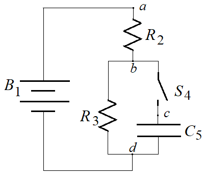
δVab = Va − Vb = V2 = I2 R2 is a statement about one device ... not a circuit!
. . . Use subscripts to identify which device each statement is about !
=> letter different locations in a circuit:
a is one end of a device, b is the other end (as high potential is relative to low potential);
=> number devices: B1 is battery #1, R2 is resistor #2, S4 is switch #4, C5 is capacitor #5
. . . this circuit is 1,2,(3||(3,4)) ... a is at R2's "high" end, b its "low" end
and a node where I splits into left branch & right branch (parallel)
... c is between switch and capacitor, d is a node where the branches rejoin .
|  |
If the Temperature changes , the resistance for many devices will change in an "almost linear" way :
metals typically have resistance that is proportional to Temperature , in Kelvin
. . . so they have twice the resistance in a 500[K] oven than they do in a −20 °C chest freezer
wires in a toaster ... their resistance goes to 4× Ro while they're glowing at 1100[K]
. . . (so a toaster's current is very large only as it starts)
and their resistance becomes very small near absolute zero (nearly superconductor).
. . . ΔR/Ro ≈ ΔT/To . . . To is traditionally 0[°C] = 273[K] , but might be 20°C
describing this (almost-constant) slope a slightly different way,
=> ΔR/Ro = α ΔT . . . where α for metals ≈ 1/273[K] = 0.0037 [1/K]
semi-conductors typically resist less at high Temperature (ρq is higher).
. . . pretending that their resistance at their working Temperature is "part of a straight line" ( | \ )
=> ΔR/Ro ≈ α ΔT . . . where for example, Germanium's α ~ −0.048[1/K] , at 20°C = 293K
. . . at that slope, α ~ −1/20[K] , would make R → 0 by T = 313[K] ... but R(T) curves, so it does not cross zero .
Ge example 1 (above): if ΔR = −R20, then that Rfinal = Rinitial + ΔR = 0 .
so ΔR / R = −1 = α ΔT , so ΔT = −1/α = (+)1/0.048 = 20.8° so Tfinal = Tinitial + ΔT = 20°C + 20.8K = 40.8°C .
. . . Ge example 2: What would that big crystal's resistance be at liquid N2 Temperature (77K)?
ΔR = R α ΔT = (5.75 Ω)(−0.048 1/K)(77K − 293K) = (+)59.6 Ω so R77 = 5.75 Ω + 59.6 Ω = 65 Ω .
... disclamer: Ge's resistivity curves up so much that its resistance at 77K would be about 2500 Ω (has a maximum there)
designed devices like various thermistors are made with resistances that increase (or others that decrease) "sensitively"
PTC's increasing to 50 R0 with ΔT=25[K] ... you choose T0 at 50°C, 75°C, 100°C, or 125°C
(or NTC's dropping to ¼ R0 with ΔT=25[K] ... smooth curve)
Circuits use Resistors and Conductors - - - - - -
Parallel : Currents in Parallel Add ... Conductance Areas in Parallel Add
Total Current going into a junction (or other device) is equal to the total current coming out of it
. . . this is true after a pico-second or so (first few femtosec, charge builds up on the surface of the solder spot...)
If the paths are parallel, they re-converge at the bottomG|| = G1 + G2 + G3 + ... .
=> 1/R|| = 1/R1 + 1/R2 + 1/R3 + ... .
Notice that Conductances carry charge "like" Capacitances ... but Resistances relate reciprocally.
Series : Voltages in Series Add ... Resistance Lengths in Series Add
Total of all the Voltages around any closed circuit (in same clockwise/ccw sense) is zero
. . . simply, the battery's Potential boost (+) is lost (along each passive route) going back to the P.S.(−)
Rseries = R1 + R2 + R3 + ... .
Current from High Potential to Low Potential Transforms Power - - - - - -
I = dQ/dt , so if the "landscape" δV remains constant along a path
. . . (due to a power supply continually replacing the charges that flow thru that path)
=> charge Q loses electric Potential Energy δU during Δt
the mobile charges collide with substrate ion cores (after being pushed by E-field for time τ)
so they hit with more Kinetic Energy than the substrate ion has (only thermal E, since they don't move).
. . . these collisions transfer Energy from the mobile charges (Electric Potential Energy) to the substrate (Thermal Energy);
a toaster wire gets hot when current flows thru it (from high Potential to low Potential).
=>  = I · δV ... = I R ² ... = δV ² /R = I · δV ... = I R ² ... = δV ² /R
I is the current thru that device , and δV = VR is the voltage across that device .
Often a variable Resistor is wired in series to control the amount of current (hence Power) that the load Resistor gets.
. . . current thru the load decreases as the variable Resistor's value increases (you turn down the loudness knob)
the load's power is = Iload Vload = VPS / (Rvary + Rload) · VPS / (Rvary + Rload) (Rload)
=> = VPS2 Rload / (Rvary + Rload)2 . . . from VPS2/R down to 0 as Rvary gets large
. . . the Energy efficiency η = Power to the load / Power from the supply
if the input voltage is constant , η decreases from almost 100% down to roughly 0% ...
A transistor is a 3-layer device , with one PN junction and another N or P layer they start to conduct when the PN turns on
typical resistance varies from about 1000 kΩ when its "base" is at 0.5 V , down to 2.5 kΩ or lower when its base is raised to 0.8 V or above
. . . The Power-Supply adjustment knob raises or lowers the base voltage (gradually, by hand)
another transistor can raise this one's base voltage very fast, so it acts as a voltage-controlled switch.
Resistor & Capacitor Circuits - - - - - -
a Capacitor has voltage because charge has accumulated on its plates,
. . . but a Resistor has voltage because charge traverses it.
a Resistor in series with a Capacitor will slow the Capacitor's charging
. . . current thru the R drops its voltage in R (not in C)
. . . but the current's charge ΔQ = I Δt changes the Capacitor's voltage.
how fast? I0 = Vbattery/R and Q∞ = V∞ C
=> looks like the current will fill the capacitor in time Δt = Q/I = RC
a big capacitor will need more time "to fill" (or to empty) than a small capacitor
. . . the more resistance to flow, the less current, so the longer it will take.
R C is the "relaxation time" for the circuit to change ... abbreviated "τ" ← "lower-case greek "tau"
UNITS: [ Ω F ] = [ Volt/Amp · Coulomb/Volt ] = [ C / (C/s) ] = [s] .
as current continues thru R, charge accumulates on C ... so the Resistor's voltage gets less steep
. . . when a swich opens or closes, everything changes most rapidly at first, getting slower and slower , after while
the Resistor's voltage goes as the time-slope of the Capacitor's voltage
. . . the Capacitor's charge finally quits changing, only as the current (and VR) becomes zero.
the difference from how it will eventually be (after ∞ time) is an exponential decay.
. . . with RC = τ is the time needed to accomplish most of the change ... 63% of the change ... all but 37% of it
=> It = I0 exp(−t / τ)
|  |
|