|
|
Phy.203 Links:
» Syllabus
» 203§2 web page
- - - Unit 1 - - -
» topic 1 (ch.20)
» topic 2 (21+23)
» topic 3 (22+23)
- - - Unit 2 - - -
» topic 4 (24)
» topic 5 (½25+26)
- - - Unit 3 - - -
» topic 6 (25+½18)
» topic 7 (18+19)
. . . here! ⇒
» topic 8 (17)
- - - Unit 4 - - -
» topic 9 (29+28)
» topic10 (30)
-- MU Physics 2 --
» MU-online
(BlackBoard site)
» 204 §2 web page
» 204 §2 syllabus
- - Off-Campus - -
» PhysicsForums
(human hw help)
» hyperphysics
(detailed e-book)
» Knight 4th ed.
(pdf download)
|
|
|
|
College Physics 2 (203) - Topic Seven Summary Notes
Science 159 (below 3rd Ave ramp) foltzc@marshall.edu don't phone - stop in!
Topic 7 (Focusing Light ; Image Location & Magnification)
Readings for Topic 7 (from Knight Jones Field) : 18.4 − 19.6
(suggested hw: Ch.18 probs 31, 35, 43, 45, 59, 77, 81;
Ch.19 questions 17, 19, 23 ; probs 7 or 9, 17, 19, 21 ; 31, 33 or 37 or 61, 63)
. . . Jove doesn't have videos for Unit 3 (sorry)
|  |
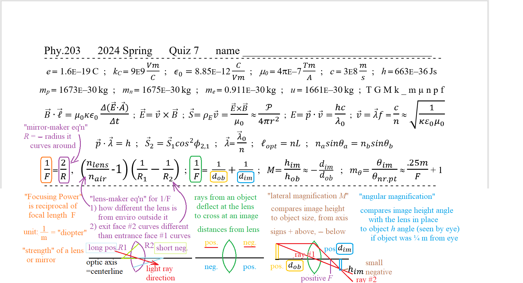
plan for Topic 7 Quiz to be thRs.Mar.14 - its header described below:
plan for Unit 3 (big) Exam to be Tue.Apr.02
Physics II Topic 7 Summary
Most of your understanding will depend on drawing the ray diagrams ;
. . . for ray deflections, remember how wavefronts are slow in material (via Huygens & Snell)
. . . all the formulas are from similar triangles (mostly opp/adj = tan θ)
Light Diverges from an Object, can be deflected to Converge to an Image - - - - - - -
Every point on the surface of an object has light radiating from it , in all outward directions
some of this light will enter an optical system - an arrangement of mirrors and lenses .
. . . If light rays really converge and intersect , due to an optical element , that intersection is called a real image ;
after the light converges at the real image , it continues in straight lines , so diverges from that => as a new object.
. . . If the light rays are still diverging , even after the optical element, the place that the rays seem to be diverging from is called a virtual image ;
(because the light is diverging , this should probably be called a "virtual object" instead , but it isn't)
Each optical element has its own effect on the light - so each lens or mirror is treated separately, one at a time.
. . . The line from the original object straight thru the optical system is usually the optical axis
Technically, the optical axis is the symmetry axis of the optical element ; we'll stick to systems with co-linear optical axes .
. . . the object's height h is measured from the optical axis, perpendicular to that axis
we choose upward as the positive direction ; out-of-the-page can be treated as lateral size , also .
=> Lateral Magnification m = him / hob = image height / object height .
. . . the object distance and image distance are measured from the optical element (outward) along the optic axis.
this requires us to make a sign convention choice . . . WE will use :
=> object at left of the lens has positive distance!
=> image at right of the lens has positive distance ... image at right of a mirror has negative distance!
implication from Snell : the Lens-maker equation - - - - - - - - - - - -
To focus parallel light rays into a point (image), rays far from the axis (@ large y) must deflect more
we want ** tan δ = y / f ** . . . for small angles, the deflection angle δ , in radians , is approximately δ ≈ tan δ .
. . . δ depends on the apex angle α of the part of the lens (y-value) traversed by that ray
for a plano-convex lens ... flat 1st surface but sloped 2nd surface "|)" ... Snell says n sin α =1 sin (α+δ) .
. . . this is a "transcendental" equation ; there is no way to solve it explicitly for δ , in a tidy formula .
but we can approximate : for small apex angles, sin α ≈ α [radians] ≈ Δthickness/Δy ≈ the tilt from vertical .
so Snell becomes n α ≈ α + δ . . . which is solvable for δ ≈ (n − 1) α .
=> to focus at focal length f , make ** (n − 1) α equal to y / f ** . . . a parabolic lens surface .
. . . (Huygens' construction shows that a parabola shape gives exact focus!)
spherical surfaces are much easier (and cheaper) to make than parabolic surfaces
the sphere's Radius is approximately − y / α . . . (because y = R sin α ≈ R α )
. . . so the curved 2nd surface has focusing power 1/f ≈ (n − 1) / −R2 .
if center of the curve is in the negative-x direction from the lens, R2 is negative , so f is positive (converging) .
. . . if the 1st surface curves also, around a center toward positive-x, then it will also deflect light to converge
the deflections add, so the focusing powers also add , for these two surfaces
. . . if they're close enough together that the light has (almost) the same y-value at each surface ,
then we get the (thin) "lens-maker" equation . . . to compute the focusing power 1 / f for a thin lens
=> 1 / f = (n − 1) ( 1/R1 − 1/R2 ) . . . lens in air (n=1) .
| 
|
For a curved mirror , parallel light rays focus at a distance only halfway to the center of the curve
=> 1 / f = −2 / R . . . the "mirror-maker" equation
 |
Usually 3 rays are sufficient to describe the character of the images formed by an optical element :
1) from the top of the object (defining hob) , diagonally downward to cross the optical axis at the optical element
the Normal to the optical surfaces there are along the optic axis, so the ray leaves at the same angle (below the axis ! ) as it came in at.
=> ray #1 is undeflected as it crosses the optic axis at the lens or mirror
2) from the top of the object , directly (rightward) to the optical element , parallel to the optical axis
this will be deflected to cross the optic axis at the element's focal length (for positive focal lengths) ;
. . . for diverging mirrors and lenses, it is only the traced-back line , parallel to the ray , which crosses the (negative) f ;
. . . for flat mirrors and flat glass , this is at infinity ... their focusing power 1/f = 0 .
3) from the top of the object , diagonally to cross the optical axis at the element's negative focal point
this will be deflected by the element to become parallel to the optical axis .
. . . for flat mirrors and flat glass , this is the same ray as ray #2.
here's a shock-wave flash playtoy to show ray #1 and ray#2 forming a Virtual image , using a flat mirror
|
Approximations ... Traditional Sign Conventions & approximations in Intro Optics : the Focus equation - - - - - - - - - - - -
If made correctly, the deflection angle δ increases with y-value from the axis (as lens-maker says above)
. . . it doesn't depend on the incident angle. (this is approximately true for rays almost parallel the optic axis)
δ ≈ θin + θout = θob + θim
. . . tan θob = y / dob ≈ θob . . . tan θim = y / dim ≈ θim .
recall that we made this lens to focus, so that δ ≈ y / f
=> 1 / f ≈ 1 / dob + 1 / dim
| 
|
here's a shock-wave flash playtoy to show Real and Virtual images formed by a single lens.
watch ray 1 (blue) , ray 2 (yellow) , and ray 3 (violet) , as you drag the object to different object distances
(notice from ray #1 that distant images are large, for large lateral magnifications) don't forget to try the concave lens, too!
Loooking at ray #1, we see that bigger images must form farther from the lens or mirror . . . they're proportional:
=> m = − dim / dob . . . for any single lens or mirror .
use the object distance and image distance from a flash lens setup , to compute the lens focal length
Application # 1 : the Camera
light from a fairly distant object is focused on a light-sensitive surface ... electronic (CCD) or film (with emulsion of metastable chemical)
. . . the image distance is only a wee bit longer than the lens focal length, so lateral magnification m = him / hob ≈ − f / dob
longer focal length lens (mounted far from the camera body on a long barrel) has a more magnified image of a smaller angular view.
Larger image size means its light Energy is spread over a larger Area, so appears dimmer (h increasing ×2 means image brightness decreases ×¼ )
. . . Energy entering the CCD Area = S·A Δt = S·h² Δt , so longer exposure time gives a brighter image
= light Energy thru the lens Area = S·A Δt = S·¼πD² Δt ... where D is the lens diameter ;
. . . brightness of Recorded Image depends on E = Power Δt ; same brightness for same ratio of (f / D)² .
f / D is called the f-number or f-ratio ; fancy camera lenses have adjustable Diameter aperature (8 overlapped triangles rotate inward)
. . . often the adjustment knob has spring-click "stops" at traditional f-ratio values (1, 1.41, 2, 2.82 ... ×√2 )
. . . f-ratio set at 16 needs 4× the exposure time as an f-ratio set at 8 . . . (8/16)² = 1/4 . . . big f-ratios mean small diameters !
small f-ratio means that all the light comes thru the lens at a small angle ... 2 f / D = tan θ actual angular diameter
. . . so the portrait background is not focused at the film distance, but the image spot size (from any one background point) is not very big: diameter ≈ tan θ · (dim− f ) .
the range of object distances that are "almost in focus" (spot size ~ 2 pixel) is called "depth-of-field" .
. . . to get a soft romantic out-of-focus background, you need a small f-ratio (<2), from a large diameter aperature in a short f lens, needing a short exposure time.
Camera : The "old standard" 35mm film Single-Lens-Reflex camera usually came with a 50mm lens (focal length), having f/-ratio ≥ 1.4 ...
To photograph a model who is dob = 2.0[m] away , what are a) image distance b) magnification c) field-of-view d) light Intensity e) depth-of-field
. . . a) 1/dim = 1/f − 1/dob = .020/mm − .0005/mm = .0195/mm => dim = 51.282mm ... the model is closer than ∞ so the film must be farther than f , to focus the image.
. . . m = 51.28mm / 2000mm = .02564 (image reduced ×1/39) . . . so object height that fits on-film is hob = him / m = 35mm ×39 = 1365mm ... (≈ 54", head-to-knees)
. . . fully-open aperature has diameter D = f/1.4 = 35.7mm , so with S = 10 W/m² from the object lets about 10[W/m²]×π/4×.0357[m]² = .0100[W] through the lens
and the intensity on the film is about .010[W]/(.035m×.035m) ≈ 8[W/m²] . . . better expose the film for at least 1/60 second !
. . . a spot in the background at distance 2½m = 2500mm focuses at dim = 51.020mm , which is (51.282−51.020=) .262mm in front of the film ;
it spreads out to be a spot Δh =(37mm/51mm).262mm = .19mm diameter on the film (this is 1/180 of the full 35mm height) ... very hazy "soft" background.
. . . digitizing this image into 1200×800[pixels] , its spot size is spread to (1200pixel/35mm).19mm = 6½ pixels diameter
. . . the 2-pixel depth-of-field is only 1/3 that far from the sharp focus . . . from 2.15m , in to 1.85m .
angular Magnification Mθ - - - - - - - - - - - - -
We're often most interested in how big something's image is on our retina
. . . the angle that image subtends (from the eye's lens, in the eyeball) according to undeflected ray #1
is the same as the angle that the object subtends (from eye's lens, in the air)
. . . the angle subtended by an object gets bigger as it is moved closer to your eye,
but there's a point at which your eye begins to strain to keep it in focus.
Using the "textbook Near Point" is supposed to be N = ¼ meter (250 mm) . . . for focusing on for extended duration
=> largest subtended angle ≈ hob / N
When one looks though a magnifying glass ... just a converging lens held close to your eye
. . . hold the object closer than 1f to the lens; light from such a nearby object diverges too steeply
so the lens cannot make them converge to a real image on the eye's side of the lens.
=> trace-back the (still diverging) rays to find the "image" ... virtual , upright , and enlarged.
. . . the image subtends the largest angle (still in focus!) at the Near Point from your eye:
1/f = 1/dob + 1/dim ≈ 1/dob − 1/N . . . notice that dim is negative !
solve for dob = N f /(N + f) , so the image at N from the lens has height him = N /(N f /(N + f )) hob
=> largest subtended angle ≈ hob ( N + f )/ N f .
Comparing this (aided) largest subtended angle with the naked-eye largest subtended angle,
. . . gives the effective angular magnification , caused by using that lens:
=> Mθ,max = (N + f ) / f = N/f + 1
. . . most textbooks follow the lens-seller approximate formula, which ignores the added "1" .
|  |
a 50mm lens can provide Mθ = 250mm/50mm + 1 = 5 + 1 = 6× (not just 5× , as textbook's formula claims) ;
. . . looking through flat glass , Mθ = 250mm/∞ + 1 = 1× , as expected for something with no focusing power (not 0× as from textbook's formula) ;
. . . my eyeglass lenses have focusing Power ≈ −2.25 diopters : Mθ = 250mm/f + 1 = .250m×(−2.25[1/m]) + 1 = −.5625 + 1 = +.438×
this is less than 1, so I'm looking at a "reduced" image thru my glasses, but their Mθ is positive, so the image I see is not upside-down!
Microscope ... looking at an enlarged real image with a magnifier - - - - - - - - - - - - -
Place the object "just farther" than the objective lens's Focal length, so its image forms at the top of the microscope barrel; calling the microscope barrel length L ,
its lateral magnification is approximately L/f ... L is the barrel length.
. . . looking at it through the eyepiece lens , at ≈feye above the barrel , makes it look bigger (to your eye) , by a factor (N/f+1)× .
=> total magnification : L/f× (N/f + 1)× . . . notice that we've ignored the negative sign, but it IS inverted.
a 16mm objective in a 160mm tube gives 10× ... with a 27mm (10×) eyepiece , produces 100× magnification .
. . . changing to a 4mm objective (40×) , the same microscope body (and eyepiece) gives 400× ($40 microscope objective, $40 eyepiece)
. . . of course, your field-of-view is reduced by 1/400× , from 114° (=2 rad) to ¼° ...
Telescope ... method #1 : looking at a nearby real image with a magnifier - - - - - - - - - - - - -
The objective mirror (or lens) produces its image at the end of the telescope barrel; the angle subtended is him/fobj , if dob ≈ ∞ .
. . . looking at it through the eyepiece lens , at ≈feye from the image , makes it subtend an angle him/feye .
=> angle subtended is increased by fobj / feye ×. . . again, it's traditional to ignore the negative sign , but the image IS inverted.
a f = 1600mm objective mirror (regardless of diameter) for a 1½ meter-long telescope, with a 28mm eyepiece, magnifies angles 57×
. . . with a 5mm eyepiece, same telescope magnifies 320× (telescope eyepieces cost $40 ; a large diameter objective costs $400)
. . . of course, your field-of-view is reduced by 1/320× , from 114° to ¼° ...
here's a shock-wave flash playtoy for a telescope (uses the 1st lens' Real image as the object for the 2nd lens "eyepiece")
(notice that the curvature Radius of the eyepiece lens changes, as you change its focal length)
... what is the object distance for that flash telescope? what is its image distance?
|