


|
|
|
- - - Unit 1 - - -
-- MU Physics 2 --
» 204 §2 web page
- - Off-Campus - - » PhysicsForums
» hyperphysics
» Knight 4th ed.
|
College Physics 2 (203) - Topic Five Summary Notes Science 159 (below 3rd Ave ramp) foltzc@marshall.edu don't phone - stop in!
Physics II Topic 5 SummaryForce qv × B separates + from − charges ... carrying their Electric Fields. . . that magnetic "Lorentz-Force" pushes any charge that moves relative to the magnetic field (its source),just like an Electric Field would, as if there was an E-field there. . . . Lorentz is easy (natural) to use when a charge is moving (+v) , but is also valid for a magnet moving −v. (eddy currents, or neutral atoms being polarized). Similar electric effects occur whenever the magnetic field intensity changes . Suppose an electromagnet has increasing current, so increasing magnetic field, and increasing magnetic flux
Faraday's Law is a "Lab Device" version of Lorentz Force - - - - - - -
Idea #10: Changing Magnetic Field makes a Temporary Electric Field :
If the magnetic field thru some Area changes, that change "induces" a temporary Electric field which encircles the Area.
|
|||||||||||||||||||||||
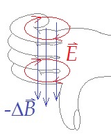 |
Jumping Ring: 450-turns in 0.15 m-long solenoid (dia= 18 mm) has I=0 (at t=0), increasing to 2 A ccw at t= 3 ms.
Topic 4 tells us that B=0 at t=0, but at t=.003 s, B3=μ0I3N/L= .00754 T (^z, up, if I is ccw as seen from above). . . . Ring has dia= 22 mm, so Φ3= B3 ·A = .00754 T (π/4)(.018m)² = 1.92 μTm² ... <= hey! 18mm, not 22mm ! . . . Topic 5 (new) says ℰ = −E·2πR= −1.92/.003 μTm²/s => ℰ = −640 μV voltage around the ring . (E= −9.26 mV/m in thick wide copper) ... Ring's resistance R= ρrL/A≈ .017μΩm (π.022m)/(.003m×.025m)= 16 μΩ => Iring= δV/R≈ −40 Amps! . . . B is up (+^z) ... ΔB is up (+^z) ... your right thumb, pointing along −ΔB is down . . . so current goes cw ... into the page on the left. Note that I in the Ring makes B down thru the Ring Lentz says that the induced current always makes a magnetic field that opposes (temporarily reduces) the flux change. |
with a z Magnetic Field weakening (as current decreases from 2A at 5ms, to 0A at 8ms)
. . . at the Ring's location, ΔB = B8 − B5 is opposite B5 ... (that is, down)
in words, the change is that the magnetic field is not up anymore . . . ΔB = −Bz .
. . . the −ΔB/Δt is now up (+^z) ... right-hand fingers wrap counter-clockwise around z-axis
=> E is induced in a circle counter-clockwise, but lasts only while B continues to change downward.
. . . the ccw E pushes current ccw ... which makes a B-field up thru the ring ... hm, Lentz was correct again.
If the Magnetic Field is −^z (downward) and increasing, the result is induced E ccw
Ratio of Voltage / Current change rate is called "Inductance" ... (proportional to reactance, reciprocal to capacitance & conductance) - - - - - -
Induced Electric fields are typically quite weak, usually less than 1[V/m] .
On the other hand: any charge that is pushed (or pulled) around a circle by Einduced will gain energy
each time it travels the circle, for as long as E exists there.
. . . If a wire coil is immersed in an induced E-field, δV increases along the entire path,
=> a coil develops ℰ = N E(2πr) . . . very high voltage merely needs a large number N of loops!
Let's look at that Jumping Ring's Electromagnet.
. . . it had the same magnetic flux change Δ(B·A) as the ring, and has a slightly smaller circumference;
so each loop's −640 μV requires −11.32 mV/m (slightly more intense than the −9.26 mV/m at the Ring's larger circumference)
. . . more importantly, it has 450× as many loops! so the solenoid's induced voltage was (−640μV/loop)(450 loops)= −288 mV
opposite the 120 V from the wall plug ... 120 V − 0.288 V = 119.712 V , reducing the current UN-noticeably.
inserting the iron core would increase ΦB ×500 ... ℰ = −144 V ? ... more than the wall ...
=> the electromagnet's current cannot increase that fast, with the iron core in-place.
Generally: any time you try to change a current (adjust a voltage knob), magnetism induces a voltage which spreads that change time-wise.
sometimes the induced voltage is small enough to ignore - but with magnetic devices it is usually important.
. . . Notice that the device's (induced) voltage arose because of the current change ... thinking of the current change as the "environment",
and the induced voltage as the device's reaction ... every other factor is a device property (N, A, R, L, ρ, μ ...)
=> ℰ = − Ldevice (Δ I / Δt) . . . L is called the device's "(seLf) inductance" ... Unit [Vs/A]= a "Henry"
A solenoid has an inductance L ≈ (μN/L)(NA) ... ×¾ if short with many layers ... for a toroidal solenoid, use L= 2πR
for air-core, use μ = μ0 ... if the core is Cr, Fe, Co, or Ni, you need to × by its relative permeability (best guess).
. . . formulas for other geometries are very poor approximations ... and pretty nasty.
you can buy tiny inductors (nH - 100μH) for a dime, and little 2mH ones for a quarter, but 50mH will cost a buck (if low resistance),
and they want $10 for ½ H ... variable inductors at a μH or less (<$3) screw an iron core into/outfrom a solenoid.
The time that it takes to change a current thru an inductor circuit is called the relaxation time (recall capacitor discharge)
. . . τ = L/R is the time to accomplish all but 1/e of its eventual change
|
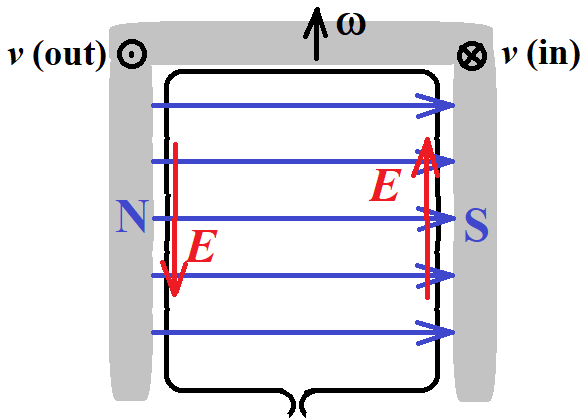
Consider N coil loops with Area A (=L× W) out of the page (+z), in a uniform B-field to the right (+x) at t=0
| 
|
the Electric Field induced along the perimeter ( ℓ= 2L+2W) ... Lorentz shows along both L portions
(to use Lorentz: the charges are seen by the magnet to be moving into the page on left, out of page on right)
. . . t = 0 : maximum counter-clockwise , strength BAω/ ℓ (this is the average E-field along the rectangle edge)
. . . t=¼T : zero ... the ccw field has decreased rapidly to zero , a cw field will grow rapidly now
. . . t=2/4f : maximum clockwise , strength BAω/ ℓ
. . . t=3/2πω : zero ... the clockwise Einduced is changing to ccw
Mobile charge in each wire loop will have more Energy at one end of the loop than at the other,
as the "circulating" Electric field does Work on the charge ... there's a voltage between one end and the other
. . . but it is not a difference in Electric Potential at two places ... the two ends are in the same place!
we need a better name for this "−Work/charge" ; the old traditional name is ℰ = "Electromotive Force"
even tho' it is not a Force (its unit is [Volt]), it exists even if there are no charges to be moved,
. . . and it's source cause is Magnetic (not Electric, like a battery's ℰ of the same name).
=> ℰ = BAω sin ωt . . . voltage at the ends of each loop.
If each wire loop is connected in series with the next one , these ℰ 's add . . . N of them, remember
=> ℰ = N BAω sin ωt . . . high voltage can be obtained
. . . If each wire loop is connected in parallel with the rest of them , their currents add
. . . but only if there's an external complete circuit
In real life, the current rises at a rate that has δVPS − L (ΔI/Δt) = I R .
. . . at t=0 , when I was starting from zero , I = (δVPS/L)·t , as a steep line.
. . . but as I increases, its slope has to decrease to make ΔI/Δt = δVPS/L - IR/L .
. . . as with charging a Capacitor, electrical quantities drift exponentially toward their eventual values (∞ time).
The quantity L that shows how much ℰ accompanies a rapid current change is called the circuit's inductance ;
L is determined ("made", theory/calculated) by the B-field per Amp made by the circuit, that gets to pierce its own Area
. . . in the example above, all the magnetic field μoI/2r inside the loop's Area πr² contributed to the ℰ ;
=> L = B·A/I . . . ok for estimates, but very difficult to use for realistic (not contrived) situations
in discrete circuits, we keep B contained in its own device , so the rest of the circuit Area does not contribute to L .
(the example above did not average B over the loop ... it's probably 30% off - L depends on wire radius! -yuk-)
L is deduced ("used", experiment/computed) by how much "back ℰ " is induced by a 1[A/s] current change rate ;
. . . in the example above, −1.6[V] was induced by a 24[A]/2[μs] = 12[MA/s] current change rate,
so its L = 1.6[V]/12[MA/s] = 0.133[μVs/A] = 0.133[Ωs] .
=> ℰ = −L ( ΔI / Δt ) tells what an Inductor does ... opposes current change by inducing a voltage (which pushes current back)
Notice that the Power Supply above was doing Work against the Inductor's Induced ℰ .
The Energy that its Work gave "to the Inductor" was stored in the Inductor's magnetic Field.
. . . recall that Energy/Volume = B²/2μo . . .
If the PS later is turned off, the Inductor will continue to pull current thru the wire
since the Induced ℰ is now clockwise just like the PS voltage used to be.
. . . the Energy to pull the current thru the resistive wire comes from the Magnetic field
(I decreases exponentially ...) until all the Energy ends up as Thermal.
A small strong electromagnet in a teaching lab might have B ~ 2[T] , average in a 1/8[m³] Volume
. . . storing (2[T])²/2/(π4E-7)[Tm/A] = 1.6[MTA/m] ... recall that [T] = [Ns/Cm] ... = 1.6[MN/m²] = 1.6[MJ/m³]
=> Energy stored = (E/Vol)·Vol = 200[kJ] is quite dangerous (1 ton @ 20m overhead) ...
humans are very poor at sensing (ignore?) intense B-fields and steep "magnetic Pressure gradient" at the field edges.
Be very careful whenever you are near large or strong magnetic fields (like MRI machines).
|
Current becomes time-dependent, oscillatory : It = I0 cos (ω t) .
here, I0 is the maximum current, which happens at time t = 0 . recall that ω is the angular frequency , in radians per second => ω = 2π [radian/cycle] f [cycle/sec] . . . . the current is (−) as much as it is (+), so obviously averages to zero but the squared current is always positive, so its average is useful the square root of that "mean squared" current has units [Amp], so is most useful : => IRMS = I0 / √2 . . . for sine or cosine current sources. |  |
|
Voltage becomes time-dependent, same frequency : δVt = δV0 cos (ω t + φ )
| |
North American Electric Grid is intended to provide VRMS ≈ 120 [V] at frequency f = 60 [cycle/s]
. . . use paragraphs above to show that Vpeak ≈ 170 [V] at angular frequency ω = 377 [rad/s] .
|
As time increases, the horizontal current arrow and horizontal voltage arrow both rotate counterclockwise (θ = ω t)
|  |
|
the Power at any time t is still |  |
Resistance R is generalized to "Reactance" X = δVRMS / IRMS . . . with units [V/A] = Ω, of course .
XR = R . . . for a resistance , reactance is just R , in [Ω] .
Because current thru a resistor is synchronized with the voltage across it, the current's phase angle is zero ;
a resistor always removes Electric Power from the current, converting it to Thermal Power, in all portions of the cycle.
. . . we draw a Resistor's Impedance phasor rightward (real positive maximum at time =0) ; its voltage phasor
will start with max (+) horizontal component ... the potential at resistor "top" is (+) max ; the E-field in it pushes I hardest toward the black wire
... the R's voltage will soon start to decrease (horizontal component), as the I phasor rotates up (ccw).
=> ZR = R . . . horizontal at t = 0 . . . (δV = I Z . . . for R , voltage drop is along the current).
Capacitance C reacts to AC most strongly at low frequency (DC) , since the Capacitor has time to collect a lot of charge.
... Small Capacitors have little plate Area ; dense charge brings intense E stretched along a big gap , so high voltage ... from small C
XC =−i/ ωC . . . in [s/rad·F] = [s·V/C] = [V/A] = [Ω] .
. . . at really high frequency , the RMS voltage across a Capacitor is very small (especially a big C)
δVRMS = IRMS X , with little time to accumulate much charge.
|
Because (+) charge accumulates on top plate until the current crosses zero (becoming negative) the maximum charge occurs then ... so the maximum voltage occurs then; Qtop or VC graph => the Capacitor voltage peaks ¼ cycle (90°) after the current peaks. (memnonic "ICE": I leads ℰ for Capacitors ) |  |
Inductors L react a lot only to quick changes , short Δt , high frequency ... especially many loops around an iron core (lots of B).
XL = ωL . . . in [Henry·rad/s] = [V·s/A·s] = [V/A] = [Ω] .
. . . at really high frequency , the RMS voltage across an Inductor is immense,
δVRMS = IRMS X , with very rapid magnetic field changes.
|
Because B and I change most rapidly as they cross zero, the inductor voltage is maximum as the current crosses zero (becoming positive). (recall the −ΔB !) Inductor voltage peaks ¼ cycle (90°) earlier than the current peaks. (memnonic "ELI" : ℰ leads I for Inductors) |  |
their total impedence (in series) becomes zero, so each can have current thru it even with zero voltage across the pair
. . . setting ωL = 1/ ωC , we find that natural resonance (angular) frequency
=> ω² = 1/ LC . . . resonance for L in series with C .
their total admittance (1/X, in parallel) becomes zero, so each can have voltage across each device even with zero total current into the pair
. . . setting 1/ ωL = ωC , we find that resonance (angular) frequency
=> ω² = 1/ LC . . . resonance for L in parallel with C . . . yes, it's the same.
If there is no "regular" Resistance, the L and C don't need the power supply anymore.
. . . the Electric Field Energy in the Capacitor (due to its +/− Q separation)
becomes Magnetic Field Energy in the Inductor,as the capacitor discharges as I thru L .
. . . The Magnetic Field Energy in the Inductor (due to the I thru its loops)
becomes Electric Field Energy in C as the current slowly drops to zero, putting −/+ Q separation on C .
. . . then the current goes the other way, as the capacitor discharges again . . . and again Q overshoots .
| maintained by Curt Foltz - email comments to foltzc@marshall.edu
... all my pages are copyright as "Fair Use" (name me as source) my pages don't use cookies, or collect any info from your browser but read this Privacy Policy for info on "www.marshall.edu" pages. | Marshall University
One John Marshall Drive Huntington, WV 25755 (304) 696-3170 | A-Z MU site index
MU Academics MU Calendars financial aid |
 t = It δVt . . . produced by current thru voltage