|
|
Phy.203 Links:
» Syllabus
» 203§2 web page
- - - Unit 1 - - -
» topic 1 (ch.20)
» topic 2 (21+23)
» topic 3 (22+23)
- - - Unit 2 - - -
» topic 4 (24)
» topic 5 (½25+26)
- - - Unit 3 - - -
» topic 6 (25+½18)
» topic 7 (18+19)
» topic 8 (17)
. . . here! ⇒
- - - Unit 4 - - -
» topic 9 (29+28)
» topic10 (30)
-- MU Physics 2 --
» MU-online
(BlackBoard site)
» 204 §2 web page
» 204 §2 syllabus
- - Off-Campus - -
» PhysicsForums
(human hw help)
» hyperphysics
(detailed e-book)
|
|
|
|
College Physics 2 (203) - Topic Eight Summary Notes
Science 159 (below 3rd Ave ramp) foltzc@marshall.edu don't phone - stop in!
Topic 8 (Light Wave Interference & Diffraction)
Readings for Topic 7 (from Knight Jones Field) : Ch.17 , 19.7
(suggested hw: Ch.18 probs 31, 35, 43, 45, 59, 77, 81;
Ch.19 questions 17, 19, 23 ; probs 7 or 9, 17, 19, 21 ; 31, 33 or 37 or 61, 63)
. . . Jove doesn't have videos for Unit 3 (sorry)
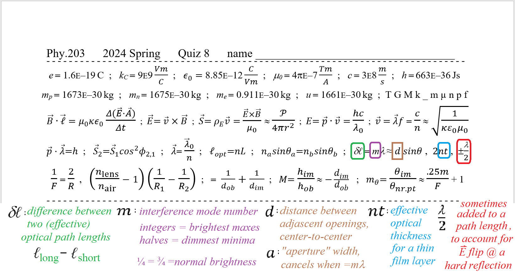
plan for Topic 8 Quiz to be thRs.Mar.28 - its header described below:
plan for Unit 3 (big) Exam to be Tue.Apr.02
|  |
Physics II Topic 8 Summary
You should always draw the rays here − their geometry shows the path-length difference ;
. . . in some situations it might help to sketch in a few wave fronts along the rays − or the E-field's wave function (like a graph of its Electric field) ;
. . . remember that wavelengths are shorter in materials (λo/n)
Idea from Physics I : Overlapping Waves Interfere with Each Other - - - - - - - -
Review Huygens' construction:
A: We treat light as a wave , with undulations of E-field and B-field pointed transversely
undulations are synchronized all along the wave-front ... a synchronized surface defines that wave-front (recall : wave front must be | S )
every point on the wave-front has the same "phase" . . . 1 wavelength away, they are also at that same phase
B: each point on the old wave-front acts as a source to induce the E at the next wave-front
(thru the ΔB at ½λ away , and ½ T later , where E is in opposite direction)
. . . the contributions from all these places reinforce each other only in the forward direction
so the wave propagates its Energy flow S (or photon momentum p) only | to the wave front.
C: consider two paths from one light-source to one detector (an eye or one place on a screen)
the source has to be in-phase with itself (there's only one of them)
. . . If the light from the different paths arrives "in phase" , they add Constructively (bigger than either) ;
they can do this if each path has the same number of wavelengths along it.
... in fact, every path that the light takes, from the object point to that point on the focused image
has exactly the same number of wavelengths.
if one path was even ½ λ longer, those two rays' E-fields would totally cancel.
this would remove the Energy from those rays, at that place, so no light would show up there. |  |
. . . the effective optical path length ℓ is related to the geometric length L by
=> ℓ = n L . . . wave-fronts deform to be closer together (lag behind) along higher index path
D: "optics design" criterion : make the difference in effective path length δℓ = ℓ1 − ℓ2 equal to zero
this makes wave-fronts converge as smooth circular arcs to form bright crisp image points
. . . the path at the lens edge travels along the hypotenuse : ℓe = nair √(r² + f²)
this must equal the path thru the center (with lens thickness t) : ℓa = nlens tc + nair (f − t)
and the path thru the lens at arbitrary height y : ℓy = nlens t + nair √[y² + (f − t)² ]
setting these equal lets you solve for the thickness t at any y . |  |
Fresnel generalizes Huygens
E: at the edge of a wave-front , the next wave-front curves around that edge
so the wave Energy spreads "diffracts" as the rays diverge from that edge.
(induced intensity goes as cos² θ , mostly forward ... zero at 90° from the old S )
F: if the wave-front has been split , "adjacent" paths might be several wavelengths different (effective optical path length)
how many wavelengths different is called the "order" m (used-to-be called "mode") ; the "Huygens path" has m = 0 .
. . . if m is an integer , the Electric fields are "again" synchronized, so they add UP , just as if they had never split off
=> constructive interference => bright Intensity
. . . if the difference in effective path length is a half-wavelength , or any odd number of ½λ , the waves are completely out-of-step
their Electric fields are opposite , so they will tend to cancel => destructive interference => minimum intensity (dim) .
=> constructive for δℓ = integer m λ . . . m= 0,1,2,3... . . . but destructive for δℓ = ( m +½ ) λ ...
Wave-Front Splitting - (light thru openings) - - - - - - - - - - - - -
Edges of an aperature split a wavefront into the part that gets thru , and the part that doesn't .
a) 2-slit (Young) ... 2 paths in air, so their effective optical path lengths = geometric path lengths ... path length difference δℓ = d sin θ at slits
d is the transverse ( | sideways) distance between centers of the openings (slits) in the mask
the angle θ , from m=0 spot on the screen to each order ... is same angle as from the mask to the wavefront
. . . for bright spots, m is just the spot count (from zero) ... the 1st dark gap is where the m value is ½ , the second dark gap is where m is 3/2 , etc.
d) many ("diffraction grating") ... can solve for Constructive Interference ONLY ... (all else dark)
=> d sinθ = integer m λ . . . wave-fronts from adjacent openings are m wavelengths apart
. . . gratings are usually labeled with their count of rulings per width N/x ... (their line density)
=> d = 1 /(N/x) . . . the more openings being used => closer to being perfectly in-step they must be
. . . "Wavelength Resolving Power" R = wmN/x = λ/Δλ ... try to use the entire grating width w !
of course its reciprocal Δλ/λ is "wavelength resolution" = d/wm ...
for 500nm visible light , a 25mm wide grating with 600 lines/mm should resolve , in 3nd order (m=3)
Δλ = λ (d/wm) = 500nm (1mm/600)/(25mm 3) = 500nm (22E-6) = 0.011nm
the yellow sodium doublet (589.592−588.995)nm =0.597nm should need less than 1mm width of grating
... but make sure mλ is at θ < 90° ! sin θ = 3 (.589μm)/(1.667μm) = 1.06 ! (oops, 500nm was at 64°)
| |
b) 1-slit (Fraunhofer) ... treat width of aperture opening a as 2 slits with centers d = a/2 apart that cancel where d sin θ = 1/2 λ , 3/2 λ , 5/2 λ ...
so destructive at a sin θ = 1 λ , 3 λ , 5 λ , 7 λ , 9 λ ...
also , treating as 4 openings d = a/4 apart , cancel at d sin θ = 1/2 λ , 3/2 λ , 5/2 λ => at a sin θ = 2 λ , 6 λ , 10 λ ...
8 openings d = w/8 apart cancels at a sin θ = 4 λ , 12 λ ... 16 pieces cancels at a sin θ = 8 λ ...
c) round "slit" (Rayleigh) ... treat as a single slit , with "average" width = diameter/1.22 . . . the interference pattern is circles , around the center spot
tall rectangle slits spread far sideways, spread very little vertically (av large so θv small)
e) reflection (Bragg) ... from "top layer" and "bottom layer" spaced t away, at grazing angle φ ... by X-rays in crystals
. . . bottom travels travels 2 t sinφ farther (with φ = 90° − θ of reflection)
Wave-Amplitude Splitting - (light partially reflected) - - - - - - - - - - -
A surface that Reflects LESS than 100% splits light into reflected and transmitted parts (all external surfaces; not total internal reflection)
detail: Reflected ray , if reflects from "more optically dense" material ... (higher n) ... flips its E-field
. . . looks like (treat it as) an additional ½λ path length . . . ¼λ IN , and ¼λ OUT
. . . if light is IN the dense matter , and reflects from lower-index material , the reflected E-field is NOT flipped.
. . . Transmitted Light NEVER has its Electric field flip as it crosses the boundary .
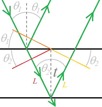
a) Thin Film Reflections ... light reflecting from 2nd surface travels "2 legs farther" than light reflecting from 1st surface
green rays are drawn here as if there is NO wavelength change ... like X-rays ; for them it is "Bragg" scattering
. . . red wave-front transmitted is synchronized with the orange reflected wave-front ... (ignoring any E-flip)
the gold wavefront reflected from bottom layer is drawn to match the orange (top) reflection's wave-front
=> so the extra path length is 2 L = 2 t cosθ
. . . if film material 2 has higher index, waves are shorter λ in it, so a ray along Normal has δℓ = n L = n 2 t ... cos0 = 1
for visible rays at non-zero θ from Normal, Snell relates the angle in the film to the angle outside the film
if θ1 is larger, index 1 is smaller, so the reflected (orange) wave-front travels faster than the transmitted (red) one:
Huygens guarantees that their intersection moves together along the interface.
... (after using 3 obscure trig identities) the bottom line is
=> δℓ = 2 n t cos θfilm . . . for thin optical films ... perhaps ± ½ λ , depending on both reflections
|  |
b) thin film coatings can enhance reflection or supress it
. . . light transmitted after 2 reflections travels "2 thicknesses" farther than light transmitted with no reflection
plus perhaps ½ λ at one of the reflections. if those 2 n t
. . . supressed reflection is same as enhanced transmission
the wave form inside the film is a resonant mode ... integer number of ¼ λ fit ... (organ pipe sound wave, guitar string wave)
maximum intensity transmits when ½-wave fits in thin film : (½λ + t + ½λ + t) = m λ
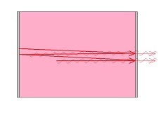
a "Lummer-Goercke plate" is a thick film with precisely parallel entrance and exit faces
usually made of glass (cleaved crystal is very expensive) a few hundred wavelengths thick, but usually quite reflective (say, 95%)
so the light travels back and forth about 20 times before it gets out. This provides "finesse" of 20.
|  |
c) Fabry-Perot ... "thick film" is vacuum or air ... n = 1 => regular λ ... t ~ thousand or million λ
. . . as surfaces are separated, the count of dim-to-bright "fringes" gives the distance, N ½λ ... (3,301,527½ fringes in Kr86 orange is 1[m])
d) Michelson ... "thick film" where the reflected part is tilted ... (usually 90°) ... from the transmitted part
. . . one runs past the park's West side and back , one runs past its North side and back ; are they in-step when they get back together?
what if ONE path ("arm") effective length is modified slightly? => ½λ's are counted
e) Mach-Zender ... like Michelson, but one goes clockwise around the block while the other goes ccw around it ...
. . . very sensitive to changes in rotation rate (e.g, Earth spinning faster in Winter)
Holography & Inverting the Point-Spread Function
Disclaimer : what the music/entertainment business calls a "hologram" is NOT a hologram -
. . . they are merely a Real image projected (from backstage) onto a translucent screen (usually mesh)
just like the old "Rear Projection" TV's popular in the 1990's (being tossed out these days)
. . . to scatter more light sideways, use mesh "threads" that are thin sideways but long back-to-front
(somewhat like the gratings for the fluorescent lights in the hallway outside Sci.277).
. . . when light hits the mesh fibers, some reflects from the (round) surface into a wide range of angles ("scatters")
a lot refracts into the fiber and then refracts out the front , into a wide range of angles.
. . . from an image focused on the mesh, all viewers in the room see the same color light
scattered to them from some spot on the mesh (true for every spot)
so everyone sees the same perspective of the image (concerts don't even "simulate 3-d" yet, that I know of).
Actual Holograms look different from different viewpoints
e.g., those to the right (left) of the hologram only see the hologram's right (left) side
Actual Holgrams are made by wave interference , after passing thru different places on the holograph
(there are transmission holographs and 2 kinds of reflection holographs ; I'll stick to transmission here).
Make a holograph : (0) split a laser beam into 2 beams (90° partial reflection at a dielectric surface)
. . . (1) one beam is spread so it reflects from all points on the object to be holographed
each point refects wave-fronts that spread in hemispheres from that point, toward the film
. . . (2) 2nd "reference" beam hits the film directly , after being spread to cover the film completely
so it will have smooth wave-fronts (often nearly flat, | to the film surface).
. . . (3) the two beams interfere constructively at rings ... (they look like Newton's rings that we saw in class)
the "exposed" film's chemicals react at constructive interference (due to E-field intensity there)
consider one object reflection point , a distance d0 measured | from film
and pretend that the reference beam ray is also | to the film (=> wavefront exactly along film).
. . . the m=0 spot is where the object ray Normal to the film meets the film ... d0 − reference distance = 0 !
the m=1 ring is at θ from this Normal ray, where hypotenuse − d0 = 1 λ
. . . that is, √(y² + d0²) − d0 ≈ d0 (1 − cos θ) = 1 λ ... and so on, for m = 2λ, 3λ, 4λ rings ...
Each reflective object point makes its own set of rings , centered on its Normal ray
with spacing that depends on its distance from the film m λ/d0 .
Display a hologram by projecting light thru the holograph (use same wavelength laser that was used to make it)
. . . the display laser wave-fronts diffract as they go through the rings ; but the rings are spaced so wave-fronts interfere.
the reshaped wave-fronts converge to the original object distance (and interfere constructively there)
. . . since there is no object there now, the wave-fronts continue, diverging from each (originally reflective) object point.
the light behaves as if the object was there - it acts like a real object optically
. . . every reasonably-sized piece of holograph will have some rings in it from every object point
so cut-in-half holograph produces the entire image (but with half the range of viewing perspective)
Idea #13 : "Heisenberg's" Uncertainty Principle
There is more structure to light than just a disturbance in the ElectroMagnetic field.
. . . Most light sources (ie, atoms) bundle a small packet of “nearly-one-frequency” waves into an envelope.
Each packet of light, called a photon, carries Energy and momentum and Angular momentum as it travels.
. . . Reminder: the Energy contained in each photon depends on its center wavelength : E = h c / λ .
A typical photon contains many waves ; the charge that made this photon did a few thousand oscillations as it re-stabilized ;
. . . the time duration taken to make the photon depends on how many oscillations it contains, and the oscillation rate (frequency)
=> Δt = N /f [(waves/photon duration)/(waves/sec)] = [sec/photon duration]
We might think of a photon as a "beat" phenomenon (recall from Physics 1) , with two slightly different frequencies
. . . At the very beginning of the photon, they're out of phase (so they cancel to zero amplitude)
... as they become not so perfectly out-of-phase, the amplitude grows until perfectly in-phase ;
as they get out-of-phase again, the amplitude dies away to zero ... tail-end of photon .
The beat frequency is the difference between the two individual contributions' frequencies
(that is, a 256 [cycle/s] tuning fork and a 250 [cycle/s] tuning fork will constructively interfere 6 times per second)
. . . a bit of algebra shows : Δt = 1/fbeat = 1/(f1 − f2) ≈ 1/(E1/h − E2/h)
associating the range of different frequencies with a range of Energies δE :
. . . so δE Δt ≈ h ... a smaller range in Energies means that the photon takes longer to make (or to pass by)
. . . you can make a single isolated pulse of wave − a photon has a roughly Gaussian-shaped wave-packet envelope −
by using many frequencies (not just two) − their intensities are roughly Gaussian , as a function of frequency.
=> δE Δt can be as small as h/2π . . . that's the absolute minimum allowed in Nature.
Heisenberg's contribution was (1) to interpret the range in frequency as an uncertainty in Energy
and the length of time as an uncertainty in when the photon was emitted (or absorbed).
. . . and (2) to derive a similar "smallest product of uncertainties" for momentum and length (spatial) :
=> δp· Δx ≥ h/2π . . . of course the photon has to be at least one wavelength long !
Waves in ElectroMagnetic fields do not act exactly the same as sound waves in “ponderous” (inertia-based) materials ;
Whenever a photon is made or detected, the entire packet is emitted or absorbed,
. . . so they interact with matter at that tiny location (way smaller than 1 λ) ... like particles.
While they are traveling, though, they exhibit diffraction (spreading out) and interference
. . . so they seem to travel as waves. This is called the wave-particle duality .
Idea #14 : Doppler Effect for Light suggests "Einstein's" Special Relativity
Recall that the Doppler Effect for mechanical waves (frequency shift for sound or water surface waves)
depended on the (relative) motion of the emitter and the receiver thru the material medium.
. . . the received frequency was different for a moving emitter, than for a moving receiver (if only one was moving).
Light can travel (as a wave) even where there is no material.
. . . an astronomer, who receives a frequency different than the star emitted, wants to deduce a velocity for the star,
which formula should they use? (moving Earth, or moving star?)
. . . a more fundamental question is: does light travel with speed c relative to its emitter,
or does it travel with speed c relative to the receiver?
Einstein recognized that (if) we use light to determine distances and durations, then the emitter and receiver will both
measure the speed of that light as the same value (c) ... even while disagreeing about Δx and Δt !
One important result from Special Relativity is the "Doppler formula" for light.
. . . it is essentially the geometric average of the two regular Doppler formulas.
(receiver's and emitter's velocities appear in an anti-symmetric manner)
(only their velocity relative to each other is used in the calculation)
=> fr / fe = √[(c − vr + ve)/(c + vr − ve)] ... relative velocity vr − ve is negative if their distance is decreasing .
|