


|
|
|
- - - Unit 1 - - -
-- MU Physics 2 --
» 204 §2 web page
- - Off-Campus - - » PhysicsForums
» hyperphysics
» Knight 4th ed.
|
College Physics 2 (203) - Topic Six Summary Notes Science 159 (below 3rd Ave ramp) foltzc@marshall.edu don't phone - stop in!
Physics II Topic 6 SummaryIdea #11, new Magnetic Field Source: - - -
|
|||||||||||||||
|
Induced Magnetic fields can be fairly strong only if the E-field changes rapidly .
||-plate capacitor example: 0.100[m] radius plates with 0.050[m] air-gap ; we will stuff 12[nC] on the plates (+ −) in 3[ns]. . t2 . its capacitance C≈ κ ε0 A/d = (1) 8.84[pC/Vm] π (.1[m])²/.05[m] =5.56[pF] => δV3=Q3/C= 12[nC]/5.55[pF]= 2160[V] . t3 . the average Indicated current I =ΔQ/Δt(x) = 12[nC]/3[ns]= 4[A](^x) brought E3= δV3/d= 2160[V]/.05[m]= 43.2[kV/m]. t1 ... or use Gauss: (E·Aout= 4πkQinside) : E3 piercing the gap Area is 4π 9E9[Vm/C] 12[nC]/(π (.100[m])²) . . t1 . E·A changes from 0 to (4πkQ3) =1357[Vm] , so E3·A/4πkc = ε0 E3·A = 8.84[pC/Vm]·1357[Vm] = 12[nC] ! . . . NOT a coincidence , it is required by Gauss' Law ... Electric Flux in the gap, rescaled to show the separated charge. new Topic 6: the Electric flux average change rate was Δ(E·A)/Δt= 8.84[pC/Vm]·1357[Vm] / 3[ns] = 4 [A] +^x . . . NO coincidence! ... just Gauss's Electric Flux growth rate, re-scaled to look like the capacitor's current +12A^x in from the left wire, +12A^x out thru the right wire ; the gap is the only place that does NOT have current flowing thru it. ... Maxwell called this the "Electric field displacement current" in the gap (it is opposite an E-field that could push the edge charges apart) . . . our new magnetic field, spread along the 2π(0.100[m]) loop at the edge of the plate gap (where strongest), comes from μ0 4[Amp] , so is => B = 4E-7 π (4[A])/ (2 π.1[m]) = 8 micro-Tesla (ccw looking from the right) ... and it lasted only that 3 nano-seconds. |  |
Unlike the induced Electric field, Magnetic Fields cannot do Work to freely-movable charges
. . . so you can't use "multi-loop coils" to "multiply" this weak and very short-lived Binduced .
But these few micro-Tesla, that only lasts for a few nano-seconds, is the basis of Topics 6, 7, and 8 ! how ?
. . . the induced B used to be "0" , before the E-field became non-zero as the charges started to arrive;
so −ΔB·A / Δt is really big for that 3 ns pulse, even though it was zero before and drops to 0 afterward.
. . . Faraday's induced Electric Field encircles the intensifying B loops near the plates' edges ... looks like a donut.
. t5 . Faraday says this induced E above the plate (+^z) encircles the plate's top edge cw as B increases
+^x outside the plates (like the growing E in the gap), but −^x inside the plate edge (opposite E in the gap)
=> the new B-field's startup temporarily reduces the original E-field (ie, delays it) ... "Lenz's Law with no conductor".
. t5 . Faraday's induced E1 = −ΔB·A / Δt 2π r ≈ −8[μT]·π 0.1[m]2 / 1.5[ns] 2π .1[m] = −267 [V/m] .
less intense, partly because it spreads thru a much larger Volume ... field patterns near a source are very complicated.
. t5 . The B·A dies away as the 3 ns pulse finishes , so the induced E turns around (at 1½ ns) for the 2nd half of the pulse.
=> the new B-field's ending will temporarily increase the original E-field, tending to make it overshoot.
You know that there used to be (at t=0) zero E-field at 2 plate radii (0.2 m) from the capacitor center-line
. . . so its change is encircled by a new B (#2), looping from plate edge to 3 plate radii
that changing B is encircled by a new induced E (#3) centered at 3 plate radii
... then a B #4 at 4 radii , and another E (#5) at 5 radii , ... etc, etc. even farther out.
=> The Electric Field Energy and Magnetic Field Energy are radiating away from the source.
Notice that this Energy density cannot be negative ... a hint that it is more "fundamental" (as a foundation) than some others.
in our example with the parallel-plate capacitor, E1's Electric field Energy density (average) was (133 V/m)²/(8πk)) = 78.5 nano-Joule/m³ .
. . . its magnetic field B2's Energy density , at the capacitor outer edge , was (99 nT)² / 2μ = 3.9 nano-Joule/m³
=> the most Energy density that this set-up can radiate away as light is 3.9 nJ/m³ magnetic + 3.9 nJ/m³ Electric = 7.8 nJ/m³ as "light"
. . . if you want to radiate more energy away as light, you need more B , so charge the capacitor 20× faster (or use an Inductor !)
if you want to radiate less Energy as "light", charge the capacitor slower !
Other Familiar Mechanical Quantities carried in Light
We can use the v formula to re-write light's Energy density: replace one E with B×v and one B with E/v
. . . ρE = u = E×B √(ε/μ) ... wait a minute ... Energy density is supposed to be a scalar (not a vector) !
even thinking of Energy density as a "potential pressure" would require a scalar ... but if we multiply by velocity
=> ρE v = E×B /μ = S is the light Intensity vector ... moving energy (density with velocity) is Power flow (vector density = Power thru per unit Area)
for light it is also called Poynting's vector (after John Henry Poynting, who figured this out in 1884)
... { Poynting taught Alfred Lotka [predator-prey model] , and coined the term "greenhouse effect" in 1909 }
. . . we use the "×" right-hand rule to find the Poynting vector direction : wrist points along E, fingers point along B, thumb points along S)
Faraday's E is always ⊥ ΔB , and Maxwell's B is always ⊥ ΔE , so sin90° = 1 , always !
. . . the Power thru that goes thru an Area is ρE v·A = S·A = ΔE/Δt ... just like charge flow or fluid mass flow .
A "100-watt" light bulb emits about 16 Watts of visible light (most is invisible Infra-Red)
. . . at 1 meter distance from the bulb, the light has spread to cover a surface that has Area 4πr² = 12.56 m²
so its intensity there is 16[W]/12.56[m²] = 1.273 W/m² .
by 2 meters distance from the source, the Area is 4× as big, so the intensity S ≈ 0.318 W/m² .
. . . light from the Sun has spread to only 1400 W/m² at Earth distance (about 1000 W/m² makes it thru a cloudless sky to Earth's surface)
the next-nearest star is 275,000× as far as the Sun, so its light is only (1/275000² =) 13 trillionths as intense.
mammal eye pupils open to admit dim light thru a larger Area (to get more Power) ; contract to a small Area in bright light.
We could have (instead) divided the Energy density by velocity ... to find the momentum density vector:
(KE = ½ p·v ... since light carries the same amount of Potential Energy , its total Energy is E = p·v )
=> p/Vol = S/v·v = ε E×B ... yes, a light wave carries momentum from source to receiver
(mechanical waves carry as much low pressure as high pressure, so transfer zero total momentum)
One last meaningful quantity in light is the momentum density divided by the velocity ... gives the effective mass density in the light's E and B fields .
=> ρm = m/Vol = u/v² = E×B √ ( ε³/μ ) ... as in E = m c²
. . . light has zero material mass ... but for each "piece of light", its Energy is confined in a small region which travels together from source to receiver;
they actually transfer mass (and Energy, and momentum, and angular momentum) as they travel from source to receiver.
=> meffective /Vol = E×B √ (μo / (4πkc)³ ) [kg/m³] .
 Δt . . . Power comes from the rate that the lamp emits photons .
Each photons' Energy depends on the frequency of its source (oscillating charge)
. . . the light's wave frequency (= photon's central wave frequency) is same as the source oscillation frequency
f is constant all during the photon's travel , from emitter to absorber (Energy is conserved!)
=> Energyphoton = h f = h c / λ . . . h = 6.63E−34 Joule·second is Planck's constant (units of "Action")
. . . one photon does 1 h of Action in each wave cycle ... say, ¼ of an e Joule × a few dozen femto-seconds
each photon also carries momentum as it travels.
. . . since light's momentum density = S / c² = Energy density / c ,
=> pphoton = E / v = h / λ . . . photons that carry more momentum have shorter wavelength
photon Energy determines its reactions with atoms & molecules => "color".
the entire spectrum of Electro-Magnetic Waves is :
(long λ , low Energy) radio - microwave - IR - ROYGBV - UV - X-ray - gamma (high f , high Energy)
... we only see the 6 "middle colors" ...
| Light Visible to humans : made as
a Valence Electron changes its PE level temporarily ... its Electric dipole moment oscillates or rotates . . . we see Red O Y G B Violet , vary less than a factor of 2 (an "octave") photon frequency range f ≈ 750E12 cycle/s → 430TeraHz ... and wavelengths λ ≈ 0.70[μm] → 0.40[μm] Vis photon momentum is from p ≈ 6 [eV·s/nano-m] → 10 [eV·s/nm] ... each photon has E = p · c ≈ 1.8 [eV] → 3.1 [eV] Ultra Violet light : made as a tightly-held electron falls even deeper into its atom (often roughly half-way)
X-ray light : made as inner electrons drop into a vacancy very close to the nucleus ... Energy ≈ "soft" 500 → 10 000 ; "hard" → 100 keV
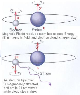
Gamma-ray light : made as a proton or neutron in the nucleus flips its spin or shifts its arrangement
a molecule bond length oscillates slower (the atom's large mass has more inertia!)
a molecule spinning slowly , with large rotational moment of inertia
electrons & protons streaming from Sun , caught to spiral around planetary magnetic fields
| 
|
After it emits a photon, the final atom has less Electric Field Energy and less Magnetic Field Energy
... which of them do you think changed by more?
"Microscopic" Details of the Field Structure in Light's Wave
In a mechanical wave, the particles having maximum Kinetic Energy are ¼ wavelength behind (or in front of) those with maximum Potential Energy.
. . . a rope wave has zero KE at its maximum excursion from equilibrium ... its KE thru equilibrium causes the next excursion.
sound has a displacement NODE at its pressure ANTI-NODE
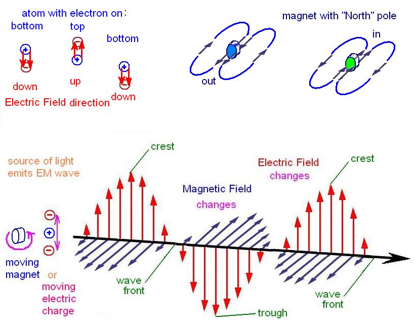
In a light wave, the maximum change in E (at its zero-crossing) will induce the most intense new B but around it − not in the same place
. . . that B will have its maximum intensity ¼ wavelength ahead of (and behind) E's zero-crossing
just where E has its own maximum intensity (same argument if you switch E and B)
In a mechanical wave, vectors for the particles are either aligned or opposite, even in a transverse wave (where they are perpendicular to the propagation direction)
. . . rope displaced upward has Force downward, had velocity upward but will soon have downward momentum; might easily have zero angular momentum.
In a light wave, an E changing to become upward has a B that is leftward in front of it, but rightward behind it ... as it travels into the page.
. . . a downward E where the B is rightward must be moving toward you, out of the page.
=> use the right-hand rule: E×B = S(μ) ... for light, all 3 vectors must be perpendicular !
Each place where and from what they were, another change (neighboring disturbance) later and further .
. . . that is the definition of a wave propagating . . . each zero-crossing is called a "wave front" . . . so light is effectively a transverse wave
Light travels very fast : v² = 4πkc / κμo . . . v = c = 3E8[m/s] in vacuum
. . . this is the rate that momentum flows thru an Area , so could be absorbed or reflected ... acts like a "possible Pressure"
=> P = p·v/Volume = S / v ... "potential Pressure" has the same numerical value as Energy density
Light momentum tends to be conserved, so it travels in a straight line (represented as a ray)
The real light rays diverge into every outward direction, from every point on the object's surface
. . . the optical definition for "object" is a place light rays diverge from.
The reflected rays can be traced back opposite their actual directions, to find where they seem to be coming from
. . . behind the mirror, these are virtual (not real) lines, since no real light rays went behind the mirror.
The virtual lines intersect at the virtual image for the original real object
. . . the optical definition for "image" is a place that light rays converge to.
because light rays do not block other light rays, every image is also an object.
When the Electric Field does work to move a molecule's charge, resistance to that temporary current can convert the KE to Thermal Energy.
less Electric field energy induces less magnetic field, so both aspects in the light are reduced by the same amount.
. . . transparent materials polarize very easily on the atomic scale, exhibiting essentially no resistance
(the valence electrons are not dislodged from their atom, just pushed a ways up the PE slope)
when the next half-wave E-field pushes the electrons the other direction, it gets that Energy back.
. . . there is a small time lag due to the electron's non-zero mass ⇒ that's why light travels slower in materials!
In particular, Polarizing Filters are plastic sheets that are essentially conductive along the polymer orientation,
(along the direction that the plastic is stretched before it solidifies).
. . . Electric fields along or against this conductive direction are absorbed,
Electric fields perpendicular to it cause no current, so are transmitted.
. . . if one component of the Electric Field Vector is absorbed, the Intensity "Poynting vector"
is reduced also , by that factor squared , since S ~ E ² .
=> Stransmitted = Sincident cos² φ . . . if the transmitted E is oriented at angle φ from incident E .
. . . this is called "Malus' Law" .
the light that does make it thru the polarizer has its E-field aligned with the sheet's transmission axis
"Regular" Unpolarized light has photons with their E-fields pointed randomly in all orientations (transverse) . . .
if only one E-field direction is transmitted, a lot of light gets absorbed ... exactly half of it (average of cos² φ )
. . . photons are allowed to be absorbed because they have "integer spin" ... angular momentum = 1 [h/2π]
electrons, protons, neutrons all have "half-integer spin" ... with angular momentum = ½ [h/2π]
the electrons (& p & n) are "Fermi-ons" ... they obey the Pauli exclusion principle, and the number of fermions is conserved.
but photons (with integer spin) are "bos-ons" ... they are not Pauli-excluded, and the number of photons is not conserved
=> photons can be created by anything that can change Electric or Magnetic fields rapidly !
this gives the photon its Energy and momentum and angular momentum ... they can be destroyed by anything that can remove these fields
. . . look at the light-source examples 2 sections above, to see where each photons' E, p, and L come from.
 |
Optical systems have the same optical length for every path thru them
|
special-case : refraction at a surface ... Snell's Law : na sin θa = nb sin θb - - - - - - -As light crosses a sharp boundary from one material into another , its wavelength becomes different suddenly .Using the wavelength as Huygen's wave-front step-size, we can derive Snell's Law. (algebra derivation uses 2 eq'ns for E--field components, & one eq'n for Energy conservation) . . . If material a ends abruptly at material b's smooth surface, we can draw the Normal ( | ) to that surface ; the light impinges on the surface with its momentum (S-ray) at angle θa from the surface Normal . . . so its wave front plane is the same angle θa from surface plane . looking at the last wavelength step in air (as passenger-side is entering the material) , sin θa = λa / hyp ... so that 1/ hyp = sin θa / λa = na sin θa / λo . . . passenger-side wavelength-step in the material is shorter (× 1/√κ) , but again sin θb = λb / hyp . ... so again 1/ hyp = sin θb / λb = nb sin θb / λo . . . it is the same hypotenuse, shared by the 2 triangles (in air and in the material) , so finally => na sin θa = nb sin θb . both ray angles are measured (ccw) from the surface Normal ; reflected and refracted rays always cross the Normal Line ! notice that if light is "trying to leave" an optically dense material, but it has too shallow an angle,
|  |
| maintained by Curt Foltz - email comments to foltzc@marshall.edu
... all my pages are copyright as "Fair Use" (name me as source) my pages don't use cookies, or collect any info from your browser but read this Privacy Policy for info on "www.marshall.edu" pages. | Marshall University
One John Marshall Drive Huntington, WV 25755 (304) 696-3170 | A-Z MU site index
MU Academics MU Calendars financial aid |